danhayes1188
New Member
we were given (4) amplifiers with one positive and one negative terminal screw on the input side of each. These were to be added(between the Leds and Power supplies) to a large sign which was powered by (4) dual lead(output) 60/120w 12v LED drivers, each pushed nearly to it's limit (79.9% capacity according to the wiring diagram we received.). The wiring diagrams, LED layouts, and instruction manual only showed how to attach these amplifiers to a single output power supply. Im new and most of our installers and techs are unfamiliar with these amplifiers. We came tothe conclusion that each output from the 4 power supplies would require it's own separate amplifier, the customer was confused by our requesting 4 more amplifiers, and had us contact the engineer for principal sloan who helped them place their order for the products we were supplied. He agreed with our lead installer's take, we would need an additional 4 amplifiers. So that's the solution we are going with.
But I am still curious what would happen if we tried to make it work with only 4 dual output PS and 4 amplifiers. Which apparently 4 other sign companies already did before us considering our customerhas been using the same wiring diagram and manufacturing order for the last 5 locations, and is now fairly upset that he has to go back behind them and verify that the signs arent burning out, we assume they used one lead only or bypassed the amplifiers all together as we did initially. Our lead told me that if we tried to use both output leads on one amplifier the voltages would cancel. This leads me to wonder if this is due to polarity. If you switched the wires so that a + and - are on the amplifiers + terminal and again a + and a - wire on the amplifiers negative terminal to reverse polarity,
(1) would this allow for current to flow to the device?
(2) would this simply overload the circuit and burn out the components?
(2a) do i have to worry about the power drawn by the controller and amplifier pushing the load past the power supplies' maximum recommended ampacity?
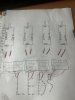
(3) is there any difference between the way one of these(see attached) dual-output power supply operates compared to two separate 60w/12v PS
(3B) does that depend on whether or not the two outputs share a neutral?
(3c) Should i think of the two output leads as 2 power supplies wired in parallel?
(4) can i check to see if the two outputs share a neutral by running a MM probe to the output leads of the PS and test for continuity?
5 does any of this make sense to someone who understands circuitry? im merely pretending to know enough to ask questions
as always please do not hesitate to callme out for my lack of understanding, just be specific so i'll know what i dont. thanks for the time it took to read this im sure it was difficult
But I am still curious what would happen if we tried to make it work with only 4 dual output PS and 4 amplifiers. Which apparently 4 other sign companies already did before us considering our customerhas been using the same wiring diagram and manufacturing order for the last 5 locations, and is now fairly upset that he has to go back behind them and verify that the signs arent burning out, we assume they used one lead only or bypassed the amplifiers all together as we did initially. Our lead told me that if we tried to use both output leads on one amplifier the voltages would cancel. This leads me to wonder if this is due to polarity. If you switched the wires so that a + and - are on the amplifiers + terminal and again a + and a - wire on the amplifiers negative terminal to reverse polarity,
(1) would this allow for current to flow to the device?
(2) would this simply overload the circuit and burn out the components?
(2a) do i have to worry about the power drawn by the controller and amplifier pushing the load past the power supplies' maximum recommended ampacity?
(3) is there any difference between the way one of these(see attached) dual-output power supply operates compared to two separate 60w/12v PS
(3B) does that depend on whether or not the two outputs share a neutral?
(3c) Should i think of the two output leads as 2 power supplies wired in parallel?
(4) can i check to see if the two outputs share a neutral by running a MM probe to the output leads of the PS and test for continuity?
5 does any of this make sense to someone who understands circuitry? im merely pretending to know enough to ask questions
as always please do not hesitate to callme out for my lack of understanding, just be specific so i'll know what i dont. thanks for the time it took to read this im sure it was difficult