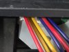
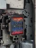
It doesn't look melted to me, it just looks like the contacts have been folded back with the white plastic backing (but still needs replacement)... Take care when connecting these multiple times, they are fairly delicate. Make sure when fitting, it's perfectly straight/flat, if anything try to slightly angle the metal contact side down when fitting (not by much, 5-10 degrees or so) when inserting (imagine the metal touching the contacts inside the connector first). That way less chance of peeling back. Hope that makes sense!
-
I want to thank all the members that have upgraded your accounts. I truly appreciate your support of the site monetarily. Supporting the site keeps this site up and running as a lot of work daily goes on behind the scenes. Click to Support Signs101 ...
You are using an out of date browser. It may not display this or other websites correctly.
You should upgrade or use an alternative browser.
You should upgrade or use an alternative browser.
Need Help Roland VS540i, Brand New Printhead Zero Nozzles firing after installing
Myster Enigma
New Member
Thank you for your response. I have had a look at the contacts and I tried to use tweezers to peel them back up but I think it may have actually melted as I couldn't unfold it. From my posts above showing my steps and what I have replaced so far does it sound like the Ribbon cable may be the issue? (no ink at all is coming through) I had noticed that the ribbon cable had this slight defect but it looked like that when I removed the old printhead so I assumed it must have been working. Also I thought I read somewhere that each ribbon cable only affects one colour not all. These are the reasons why I didn't change them early on. What is your advice.It doesn't look melted to me, it just looks like the contacts have been folded back with the white plastic backing (but still needs replacement)... Take care when connecting these multiple times, they are fairly delicate. Make sure when fitting, it's perfectly straight/flat, if anything try to slightly angle the metal contact side down when fitting (not by much, 5-10 degrees or so) when inserting (imagine the metal touching the contacts inside the connector first). That way less chance of peeling back. Hope that makes sense!
Also thank you for the tips. It has been a nightmare constantly connecting and reconnecting these multiple times as I have been testing different printheads. I have been connecting a corner first then the other corner but I know this is wrong so will do it the way you describe.
Thank you
Myster Enigma
New Member
Hi again guys,
So today just before I left I managed to replace the ribbon cables and I was extremely happy to see the nozzle test actually firing") Turns out the one bad ribbon cable had caused the head not to fire at all.
Turns out the one bad ribbon cable had caused the head not to fire at all.
So after installing I ran one nozzle test which is shown in the first photo. I ran several medium cleans and a powerful clean. The nozzle checks got worse each time. Whilst running those cleans I've noticed the small air bubbles are still in the lines and they do not move after all of those cleans. Now that I have the head firing what should I do here? I haven't had time as I had to leave early today but I am thinking I should prime the dampers again and do a medium clean. If this doesn't work do you think I should select fill ink in the service menu?
I feel like I'm nearly there now and just need to sort out the air in the lines, perhaps this was caused be me constantly removing the printhead.
Thank you again and once this is finally sorted I will be very happy.
So today just before I left I managed to replace the ribbon cables and I was extremely happy to see the nozzle test actually firing
Turns out the one bad ribbon cable had caused the head not to fire at all.So after installing I ran one nozzle test which is shown in the first photo. I ran several medium cleans and a powerful clean. The nozzle checks got worse each time. Whilst running those cleans I've noticed the small air bubbles are still in the lines and they do not move after all of those cleans. Now that I have the head firing what should I do here? I haven't had time as I had to leave early today but I am thinking I should prime the dampers again and do a medium clean. If this doesn't work do you think I should select fill ink in the service menu?
I feel like I'm nearly there now and just need to sort out the air in the lines, perhaps this was caused be me constantly removing the printhead.
Thank you again and once this is finally sorted I will be very happy.
Attachments

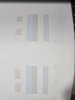
Glad the head is firing now. You need to work out why air is getting into the dampers. Try priming them and see if you can get all the air out, then run some cleans and do a test print by making up some artwork of 3" tall stripes of each colour across the width of the vinyl.
If you still getting air bubbles then you need to investigate more and find out where it is getting in
If you still getting air bubbles then you need to investigate more and find out where it is getting in
Myster Enigma
New Member
Thank you. Yes I will prime them tomorrow morning and print some stripes to see if they draw some ink down. It seems a bit intermittent. At times before the ink will run towards the head and sometimes it doesn't so not sure why that is. Do you recommend to do fill ink if priming the dampers doesn't help? ThanksGlad the head is firing now. You need to work out why air is getting into the dampers. Try priming them and see if you can get all the air out, then run some cleans and do a test print by making up some artwork of 3" tall stripes of each colour across the width of the vinyl.
If you still getting air bubbles then you need to investigate more and find out where it is getting in
Jim Hancock
Old School Technician
Have you tried doing a choke clean to prime everything?
Myster Enigma
New Member
Thanks guys. Today the first thing I did was a choke clean. I looked at the lines and the ink did not move at all. I did a test print anyway and it was the same. So I primed all the dampers (filled up a 10ml syringe twice per colour) and the ink lines are completely solid. Did a medium clean followed by another choke clean. So the nozzle checks got worse and worse each time with cyan being the only solid colour on both channels and black dropping out completely.
So Cornholio with the cap postition what do you mean about it's position? When I change the cap top I go on the Youtube video from Stahl's and thought that there was only one way to put the captop on. I'm not wondering if it's possible that I installed it at the wrong position? Ink is going to the waste ink bottle.
Also my recent pump is a lot quieter than the one that I replaced. Is this normal.
Any idea what I should do next?
Thank you guys and again apologies as I am sure it is frustrating for you guys to hear as well
Attachments
Cap position front back is a mechanical adjustment of the whole cap mechanism.(should be left alone normally)
Left right is by the plastic part, that the cap is mounted on.(probably deformed?)
You say ink is going to the waste tank during cleanings, but is it enough, or is there air sucked in as well? (I think there is a table in the service guide of how many ml are used for each cleaning type. You could check that. I just see it from experience(after this many years), if it's not good...)
Is the waste ink foamy? (Happens, if you get air in.)
Myster Enigma
New Member
Thanks Cornholio,Cap position front back is a mechanical adjustment of the whole cap mechanism.(should be left alone normally)
Left right is by the plastic part, that the cap is mounted on.(probably deformed?)
You say ink is going to the waste tank during cleanings, but is it enough, or is there air sucked in as well? (I think there is a table in the service guide of how many ml are used for each cleaning type. You could check that. I just see it from experience(after this many years), if it's not good...)
Is the waste ink foamy? (Happens, if you get air in.)
Yes the cap mechanism I have never messed with so that should be fine. I think you might be right with the waste ink cleanings. It may not be enough, I have never checked in the past how much ink comes through during each clean but when I am doing several medium cleans there's probably like 10ml after 4 cleans. Surely there should be more than that. I will have a look at the service guide later on. The ink isn't foamy at all though. I have reordered a genuine captop and pump along with 4 more dampers just to be sure I can rule that out this time. I think initially I was concerned with the printhead firing. I will let you know how it goes once installed. Hopefully this nightmare will be over
Myster Enigma
New Member
Hi Everyone. Sorry for the late response as I actually moved home during this whole issue with the printer and haven't had time to post back. The issue was the ribbon cable!!! After all that I bought new ones as suggested and the heads are all working fine So if anyone has this issue and even if one ribbon cable is damaged it will not fire any nozzles. Initially I thought that only some colours will not fire so I was reluctant to change the cables. Again thank you for your help. Could not have done it without you guys
So if anyone has this issue and even if one ribbon cable is damaged it will not fire any nozzles. Initially I thought that only some colours will not fire so I was reluctant to change the cables. Again thank you for your help. Could not have done it without you guys