• I want to thank all the members that have upgraded your accounts. I truly appreciate your support of the site monetarily. Supporting the site keeps this site up and running as a lot of work daily goes on behind the scenes. Click to Support Signs101 ...

media comp grey lines not straight?

Kinkajou

New Member
Hi.
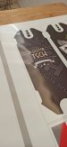
I'm having a light banding issue so I started a media compensation test. Current value is 0. I noticed that at the start of the print, on the far right, the lines do not touch. They start touching near the far left of the paper and then, at the end, overlap. How is that possible?
What should I do?
I'm running this test o a Mimaki CJV150-160 and Avery Dennison MPI 2006 (high tack). Heaters 40 40 50.

EDIT: just some additional info. I replaced my print head some months ago with a compatible one. Maybe it was not installed totally straight?
 

Attachments

  • 1628160285463.jpg
    1628160285463.jpg
    490.8 KB · Views: 357
  • 1628160285490.jpg
    1628160285490.jpg
    311.5 KB · Views: 143
  • 1628160285516.jpg
    1628160285516.jpg
    249.5 KB · Views: 186

balstestrat

Problem Solver
Do you mean that on one single value there is overlap on the other end and gap on the other?
Did you do all the adjustments to it correctly when you installed it?
What if you take a good picture of your nozzle test and lets start with that.
 

Kinkajou

New Member
Did you do all the adjustments to it correctly when you installed it?
What if you take a good picture of your nozzle test and lets start with that.
I did not. My technician did! Here's my print test. I have 1 missing nozzle. It's not going away since May, I think...
 

Attachments

  • enohJeEw.jpeg
    enohJeEw.jpeg
    944.1 KB · Views: 190

Kinkajou

New Member
Ok seems good. So lets get back to my original question.

Do you mean that on one single value there is overlap on the other end and gap on the other?
Like on this 0 value, there is gap and overlap both?
Yes, with Value: 0 there is gap on one side (right) and overlap on the other (left)!
 

Kinkajou

New Member
Also this... it is normal that if I print a rectangle with these dimensions: width: 24cm; lenght: 66cm the resulting prints is 23,9 cm x 66cm?
 

Solventinkjet

DIY Printer Fixing Guide
Either your head is slanted or the Y bar had been bent. You probably just need to run the head slant in service mode. It's a physical alignment so either it was always out of whack or recently you had a nasty head strike and knocked it out of whack.

If it's a bent Y bard it's basically like a totaled car. Not worth fixing. The bar doesn't bend easily so it't very rare but if you are one of those traveling types who throws it in the back of a trailed and sinch it down real tight, that will bend the bar.
 

Kinkajou

New Member
Either your head is slanted or the Y bar had been bent. You probably just need to run the head slant in service mode. It's a physical alignment so either it was always out of whack or recently you had a nasty head strike and knocked it out of whack.

If it's a bent Y bard it's basically like a totaled car. Not worth fixing. The bar doesn't bend easily so it't very rare but if you are one of those traveling types who throws it in the back of a trailed and sinch it down real tight, that will bend the bar.
Maybe the head misaligned after a light hit with media some months ago (couple of months after changing it). I'll call my technician then.
The Y bar problem is what's causing the print to be shorter by 1mm?
 

balstestrat

Problem Solver
Most print materials are going to experience some stretch/shrinkage on the length side of a print. Ideally the printer has a built in adjustment that fixes it, but real world experience tells us to add a bit of margin to anything on the length, or for more precision type work, figure out the difference as a percent, and modify your prints when designing or ripping to accommodate this shrinkage. So here it would be 23.9/24 = 99.58%, so inverse of 99.58 is 100.42%
So lucky with the numbers here :clapping:
 

Kinkajou

New Member
Most print materials are going to experience some stretch/shrinkage on the length side of a print. Ideally the printer has a built in adjustment that fixes it, but real world experience tells us to add a bit of margin to anything on the length, or for more precision type work, figure out the difference as a percent, and modify your prints when designing or ripping to accommodate this shrinkage. So here it would be 23.9/24 = 99.58%, so inverse of 99.58 is 100.42%
This is witchcraft. So I cannot export a pdf with fixed size and expect the printer to print what I want? sigh...
Also... I still have a big problem with mismatching cut holes.
This is a laminated print (hi tack + R10 lamination) with holes for screws. When applied to plexiglass with soap&water, it shrinks causing the mismatch. Is this because of the 1mm error of the print?
I told my customer that the best way to achieve 100% precision is to cut holes manually with a precise cutter, he won't listen to me.
 

Attachments

  • WhatsApp Image 2021-08-04 at 11.30.42.jpeg
    WhatsApp Image 2021-08-04 at 11.30.42.jpeg
    283 KB · Views: 170
Last edited:

Kinkajou

New Member
You said the lenght is the same so no, seems like that's just the material shrinking.
It's the height. Prints are shorter by the height... I print in two ways depending on which board I have to print. Larger don't fit horizontally, so I flip them and print as you can see in the following attachment. Red line is the shrink of 1mm
 

Attachments

  • 534.JPG
    534.JPG
    49.9 KB · Views: 135

Kinkajou

New Member
Ok, let's not use height in this conversation for clarity's sake. Width will be the width of the material as it comes through the printer, your 137cm edge here. Length is the amount of material on the roll. The length is what is consistently shrinking, ideally you can nail that down as a percent, and not mess with the width if it's spot on. This is purely a function of heating and cooling the material as it runs through the printer.
Additionally, you may have shrinkage from the type of product. Calendered stuff will shrink, cast stuff much less so, but there is still shrinkage. Some polycarb materials don't shrink as bad, though I'm not certain that they'd be superior to cast films.
Additionally (again), laminating your prints with too much tension will cause stretch, or really even slight tension. The only way to completely alleviate that would be mounting the graphics first, then laminating the substrate, which is a potentially a production/logistical impossibility.
As far as getting holes to hit precisely where you want them, you may need to look into something like a flatbed UV printer... Or add a sort of margin into your graphics in case the hole and the blank part of the print don't exactly align.
Okay, I'm starting to understand the situation... I generally cut console skins from oracal cast vinyl, thick texturized vinyl or prints on cast vinyl which are then laminated with cast laminate, they comes out always perfect, with holes for buttons and screws corresponding precisely.
This is the first time I print on high tack, laminate with thick ant-slip vinyl and then cut. It is a delicate job that does not admit mistakes to obtain maximum precision.
Now my customer asked me to compensatethe misalignment of the holes by moving their cut path on illustrator accordingly. Is this a true solution? I'm still thinking that it's way better to install the graphic with no holes and then cut them manually.

Before knocking at my door, my client got supplies from a guy who did direct UV printing on non-slip film. He was able to cut holes with a countersink without ruining the vinyl. He tried to countersing my laminated prints and the lamination was destroyed!
 

jfiscus

Rap Master
In this case it could be the plotter's accuracy affecting the final product in addition to the printer's size accuracy. They have their own X/Y calibration adjustments similar to the printer.
 

Kinkajou

New Member
You may want to find out what laminate the UV printer was using, as that sounds like the true issue at hand. Aside from the actual behavior of the film once they are printed with the different inks. Solvent prints leave the media a little softer/gooier adhesive, latex heats it up to the point of noticeable stretch, UV tends to harden more and remove some stretching capabilities. This may be where you're getting poor results, at least with countersinking the holes...
Surely you're wanting to some of the graphics register to the buttons, but at the same time surely some of your prints aren't necessary to register, like a camo or pattern type of skin. For those you could forgo registration and just oversize your prints.
Former supplier don't use any laminate. He (poorly) print directly on anti-slip film and deliver the product to his client. My product thanks to the lamination and the high quality print is better, I think...
Plotter cuts where I tell him to cut, I made tons of tests with square and circles. The problem is that he prints and therefore cuts 1mm shorter every time, so this causes the holes to be misaligned.
Board from side to side is 20,65 cm, actual result is 20,55 cm. We'll see now with the manual correction of the vector file, provided that now the plotter ALWAYS prints 1 mm shorter!
Oh, I even started using multiple registration marks to make the cut even more precise, but it didn't help.
 

Attachments

  • gf.JPG
    gf.JPG
    17.5 KB · Views: 126

Kinkajou

New Member
In this case it could be the plotter's accuracy affecting the final product in addition to the printer's size accuracy. They have their own X/Y calibration adjustments similar to the printer.
Already did X/Y cut calibration. Still getting the problem. I'm seeing my technician at the end of the month...
 

Kinkajou

New Member
I don't f... believe it. Now my 23 cm x 63 cm prints are actually 23 cm x 63 cm. Just now that I manually moved cut holes by 1mm to compensate!
What I did different? Less heat (45-40-45 instead of 45-45-50), I checked a little box in cut menu that says "keep 100% proportion" and expanded the outer rectangle instead of keeping it a line (see attachment).
I'm still printing... I'll let you know but we'll know if this worked or not on Monday, when my client applies the prints to the boards...

(and sorry for my english, I'm Italian)

EDIT:
WhatsApp Image 2021-08-06 at 17.26.56 copia.jpg
first print was NOT aligned to center of paper. Size is correct.

WhatsApp Image 2021-08-06 at 17.26.57 (1) copia.jpg
second print was aligned to center of paper. Lenght is smaller by 1mm, again.

WhatsApp Image 2021-08-06 at 17.26.57 copia.jpg
third print (24 x 66), aligned to center. Result: 24 x 65,8 2mm shorter.
 

Attachments

  • WhatsApp Image 2021-08-06 at 17.00.11.jpeg
    WhatsApp Image 2021-08-06 at 17.00.11.jpeg
    95.7 KB · Views: 139
Last edited:
This is witchcraft. So I cannot export a pdf with fixed size and expect the printer to print what I want? sigh...
Also... I still have a big problem with mismatching cut holes.
This is a laminated print (hi tack + R10 lamination) with holes for screws. When applied to plexiglass with soap&water, it shrinks causing the mismatch. Is this because of the 1mm error of the print?
I told my customer that the best way to achieve 100% precision is to cut holes manually with a precise cutter, he won't listen to me.
It looks like the Avery MPI 2006 is a calendared vinyl, cast vinyls don't shrink as much. I always add or bleed my edges if I'm using a calendared vinyl.
 

Kinkajou

New Member
With manual correction, now cut holes do match.
 

Attachments

  • WhatsApp Image 2021-08-11 at 10.11.08.jpeg
    WhatsApp Image 2021-08-11 at 10.11.08.jpeg
    589.9 KB · Views: 120

Kinkajou

New Member
Huzzah! Be aware as time goes on you will likely have to recalibrate, so make note of the procedures for future calibration.
Uhm, I did not calibrate anything on plotter side. Just moved cut path for screw holes 1mm here and there. Anyway... yesterday I printed on blueback paper. Did a media comp. test and the grey lines were 0,1mm apart with VALUE:0, so I set it to -10. Also, banding disappeared.
W-i-t-c-h-c-r-a-f-t.
 
Top