• I want to thank all the members that have upgraded your accounts. I truly appreciate your support of the site monetarily. Supporting the site keeps this site up and running as a lot of work daily goes on behind the scenes. Click to Support Signs101 ...

JV3 heater wiring - voltage

genericname

New Member
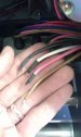
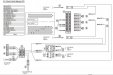
Doing some routine maintenance, I reinstalled some hardware on the JV3 after cleaning around the heads, and my hand every so lightly bumped up against the wiring for the voltage selector, located on the underside of the machine, at the far left side. These are the selectors that allow you to switch between a 220V and 110V source.

Anyway, I guess one of connectors was fatigued, as the brown wire on the selector closest to the front, on the left, just came off its seat without warning. Broken right at the base of the selector's plastic, I had to dig a bit to get the broken metallic lead out, and I'll be bringing my soldering stuff in tomorrow to see if I can replace it.

If replacing it doesn't work out, I know I can bypass the switch altogether and just short the proper wires together, since I'll never be switching from 110V to 220V anyway. Problem is, I have no idea which coloured wires I'm suppose to short.

Anyone have any clue? I know White is neutral, so that's in the equation no matter what, but that still leaves Black, Brown, and Red.

:help
 

Attachments

  • IMAG0671.jpg
    IMAG0671.jpg
    33 KB · Views: 214

artbot

New Member
it's greek to me but maybe someone that is good with electricity on the board can decipher it.
 

Attachments

  • jv3 heater diagram.jpg
    jv3 heater diagram.jpg
    59.3 KB · Views: 186

genericname

New Member
To wrap the whole thing up, I got her up and running again, seemingly without issues.

Fortunately, I was able to fashion a new lead by tearing apart an old motherboard CD audio cable, and it worked well when feeding it back into the switch for the print heater's voltage selection switch. The trick is that the pins don't just sit in there, but once they're inserted, they need to be bent forward, creating a flat surface on which the switch moves its contacts to short the connection.

When tearing the switch apart, I was able to pull all the wires (with exception of the busted one) with their leads fully intact. Pulling them through the plastic housing of the switch flattened them out, but bending them back into position was easy enough when reinserted. I just took a pin, and angled it into the opposite end of the switch, rocking it against the lead in order to flatten it into position.

I already took note of the positions of the wires, and there is an identical setup on the switch next to it anyhow. That gave me an idea though, as I'd lost the positioning of the contacts once reinserted into the switch (there are two metal bridges that close either two separate circuits, or only one depending on the switch setting). Carefully pulling apart the switch next to the problem one, I could see in which position the bridges were, and just rebuilt the original switch with the same configuration. Looks like Black shorts to Brown, and White shorts to Red. Thanks to this, I didn't even have to worry about metering the wires; it was just a matter of copying what was already there.

Re-mounted the switch plate, closed up the printer, and powered on. I have heat, and no warning messages! Hooray for happy endi- wait... fortuitous... conclusions!

:thumb:

Below, for future reference, are shots of the partially assembled switch, and the selector position relative to the position of the bridges. With a front facing switch (White arrow facing the front of the printer), the dot should be lining up both with the arrow, and the center of the switch, between the two gates on the narrow end.
 

Attachments

  • IMAG0675.jpg
    IMAG0675.jpg
    28.4 KB · Views: 207
  • IMAG0677.jpg
    IMAG0677.jpg
    23.8 KB · Views: 185
Top