• I want to thank all the members that have upgraded your accounts. I truly appreciate your support of the site monetarily. Supporting the site keeps this site up and running as a lot of work daily goes on behind the scenes. Click to Support Signs101 ...

UJF 6042 MKi blowing out X motors

btxmedia

New Member
This is the second time my 6042 has fried it's X motor. Last time was about 2 months ago. It starts out as giving random X CURRENT errors after a job is done as it goes to park the carriage at the origin. Never during a job. This motor gave the error 2 times before then burning out.

Any ideas what it could be?

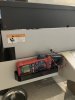
The motor connects to the mainboard on CN14, encoder is on CN15. None of the wires or connectors look bad. If the MOSFET bridge on the mainboard that pulses the motors were stuck or bad it would never work. The chances of it randomly sticking after all this time are low.

Power supply voltages are in range on both power supplies for the +35v lines. But I think it's only the main supply that powers the X motor anyway.

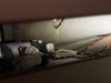
I am going to clean and oil the side rails, and also clean out all the grease on the linear bedscrew the X motor drives. Then relube it with Mobilux EP1. My thinking is as the X motor rehomes the carriage it's either hitting a tough spot or getting some resistance near the end deceleration, which is either causing it to overdrive the motor or make regenerative power. Hence the X CURRENT error only on that spot.

Additionally, I may move the origin down the bed 3 inches to prevent the carriage from having to travel on that part of the rail if there is a rough spot. Wouldn't prevent the hard deceleration though.

Firmware is 1.9, looks like ChatGPT claims v 2.4 fixed a deceleration issue so maybe this was a known bug. Of course Mimaki in their infinite wisdom does let us mere mortals have access to such things like service manuals for their unsupported models so I'll stay at 1.9.

I have another spare motor, power supply, and mainboard ordered in any case. My plan is after cleaning put a new motor in and jumper the cables to a voltmeter and just leave it running to see what voltage happens. Motor is rated at 24V so anything appearing on the lines over gives a clue. If that fails again all I can think is change the mainboard/power supply.
 

Solventinkjet

DIY Printer Fixing Guide
Here's a better way to test the motor ICs. Just to rule it out in case they can be malfunctioning in a way that is damaging the motors. Also, I looked through the firmware history and there aren't any motor fixes mentioned so GPT might be confused.

Test.jpg
 

btxmedia

New Member
Nice thank you very much. The 6042/3042 is not exactly as pictured but I found the relevant portion.

I'm testing the 2 mainboards I have but the resistance values are nowhere close to 10K ohms. I'm getting 500-800K ohms on all 8 one each board. All other parts look good visually. I will attempt to check them in diode mode, perhaps that's what Mimaki was wanting.
 

Solventinkjet

DIY Printer Fixing Guide
Nice thank you very much. The 6042/3042 is not exactly as pictured but I found the relevant portion.

I'm testing the 2 mainboards I have but the resistance values are nowhere close to 10K ohms. I'm getting 500-800K ohms on all 8 one each board. All other parts look good visually. I will attempt to check them in diode mode, perhaps that's what Mimaki was wanting.
Yeah, they've changed the boards a lot through the years. This machine isn't my specialty but maybe Smoke_Jaguar has some insights. He's the expert.
 

btxmedia

New Member
They are irfz44n MOSFETS, and in diode mode all 8 give a healthy 0.53V. So I think they are ok. Unless I can find some more tests I am going to assume the driver chips are good.
Smoke_Jaguar will likely have a DIY arduino powered motor controller he hacked for 5% faster printing or something.
 

btxmedia

New Member
I tested them for Gate Source leakage and all 8 checked out consistently, so I think they are good. Will proceed with deep cleaning the rails/screw and swapping motor.
 

btxmedia

New Member
I know when I'm not wanted. =P
You're always welcome!

In theory you could disassemble the firmware. The take an educated guess where the alarm function is by looking for the ASCII message codes or the 401/404 code placeholder. Then see what reference value for voltage it's checking against before jumping to the alarm, to at least get a sense of what value triggers it. The motor is rated at 24V but it's using 35V so it's not pulsing more than 70% of the voltage. It shouldn't ever pulse more (I would assume) unless that motor is going bad, or the MOSFET is randomly sticking, or there is something blocking the rails. Just spitballing.
 

btxmedia

New Member
Beyond bearings that have ground out, or a burned coil, I am not sure what me personally would be able to tell. I have to treat a motor as a black box. Both motors smell like burned out chemicals if that means anything special.
 

btxmedia

New Member
I have lubed the rails and cleaned out the ballscrew (#29 in pic), then relubed the ballscrew with Mobilux. In theory #29 can be unscrewed from #23 for complete cleaning. However it looked too hard to do.

Reattached a new motor and it works. I tried measured resistance and diode testing on the new motor, but honestly I don't know what I'm doing there, so not much to report.

Putting the belt back on I made sure it wasn't too tight. The service manual in the "X Reducer Assy" sextion 6.3.8 says 6-7mm gap on frame holder. The belt dimples a few mm when I touch it so it's not tight.

Next is to copy all system paramaters in case I have swap motherboards eventually.

Also, I made a mistake in my thinking. I had assumed X CURRENT ERROR meant incorrect voltage. I now think it means too much Amperage. Seems like motors can draw too much current (amps) if they are failing internally, have too much friction/resistance on the drive train, run into something, etc. Basically need to work harder than normal. This setup of a ballscrew and screw rail being driven by a motor is also used in mills/lathes/cnc. And many reports of drive motor current errors in that world.

So now it looks like I need an ammeter installed with the motor wiring so I can see what's happening, instead of a voltmeter. Also to take the front case off and nuke the annoying speaker or wrap it in some felt.

6042screw.png
 

btxmedia

New Member
It could also be the X origin sensor. It's a photo sensor mp-oj-6505-n2. If it was failing it might not relay it's sensing the metal carriage flag soon enough. Which would cause the x motor to keep pushing the carriage back until the ballscrew slams into the driverail bracket (part #25). This would overamp the motor. When a job is done and the carriage returns to the back there is only about 3-5mm of clearance between the two. And the error was happening after a job end. Setting a new x origin doesn't affect this, that just changes the print start I think.

I am going to swap it out with a new one as a cheap insurance policy.
 

btxmedia

New Member
Swapped the photosensor. Also build a motor extension cable from the connector on a dead motor + a JV33 motor cable. It's run through a hole drilled in the front cover. And then runs back to the motor mount. I have a clamp DC ammeter on the red wire exposed in the front now.

Showing around 3.4A current when jogging and 0.45A when held idle. The idle number might actually be lower due to a 0.15A baseline even when turned off from interference, etc. Maybe this will be useful to someone else. Power supply maxes at 5A, I think these are 4A motors so there's a point of reference it should never exceed. If it does the X motor is going to fry.
 

Attachments

  • Photo Jul 05 2025, 2 23 04 PM.jpg
    Photo Jul 05 2025, 2 23 04 PM.jpg
    1.5 MB · Views: 9
  • Photo Jul 05 2025, 2 22 28 PM.jpg
    Photo Jul 05 2025, 2 22 28 PM.jpg
    1.6 MB · Views: 9

netsol

Premium Subscriber
i am a rank amature when it comes to mimaki, BUT
we are not troubled by .45 aMP CURRENT with the motor doing NOTHING?
seems a bit odd to me (could just be me)
 

btxmedia

New Member
i am a rank amature when it comes to mimaki, BUT
we are not troubled by .45 aMP CURRENT with the motor doing NOTHING?
seems a bit odd to me (could just be me)

I don't know enough about motors to answer if it's normal. I will make some more readings next week and report back. Maybe I misread it and the baseline interference is higher, or maybe my new loop reads strange. Another way to test would be to swap a new mainboard in and see if it sends the same idle current.
 

netsol

Premium Subscriber
a continuous .45 amp of current DOING NO WORK should be producing a fair amount of heat.
pit also needs to be disapated. There should be, to my thinking, a heat sync or the motor itself getting fairly hot.

smoke jaguar would be able to answer this this better than I can, though
 

Smoke_Jaguar

Man who touches printers inappropriately.
Not uncommon for motors to be pulling constant amperage when on to maintain position or braking. .45A at 24V is ~11W, or ~21W at 48V. Not a huge draw for these motors, and to be expected.
 

Vassago

Been here a while..
Servo motors draw current to remain in position unlike standard motors. Hence the small current draw. See if the current increases if you push it with your finger.. It shouldn't move and the current should rise.

Test the psu voltages in AC mode.. Make sure no caps have failed.. Shouldn't have much AC present on dc lines. If you do, could be a bad psu
 

netsol

Premium Subscriber
Servo motors draw current to remain in position unlike standard motors. Hence the small current draw. See if the current increases if you push it with your finger.. It shouldn't move and the current should rise.

Test the psu voltages in AC mode.. Make sure no caps have failed.. Shouldn't have much AC present on dc lines. If you do, could be a bad psu
am i incorrect they would draw current to stay in position AGAINST A LOAD? for instance if the movement was vertical and gravity acted on carriage weight.

1/2 amp is a fair amount of heat to "piss away" standing still.

you mention a really good point, though, is this a situation where some of the caps (or just one) has high ESR?

do you think it would help if i offered to loan him an analog ESR meter (there is a lot to be said for a simple GO - NO GO test)
 

Vassago

Been here a while..
Unfortunately it's not that simple as if you touch a servo motor you'll notice a slight vibration - this is because the motor is trying to move to the commanded position, yet there's always a slight overshot (inertia of mechanical components) - so it's usually never "Exactly" at the right point so oscillates slightly (fractions of a mm) - whilst a stepper motor has discrete steps.

500ma is nothing when you consider the moving mass it's constantly trying to keep in position - even if it's not "moving".

An ESR Tester would be a good idea.. Most issues usually have a PSU fault to start with.
 
Top